BRIX₂ Base Module
Overview
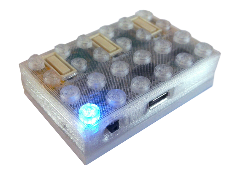
The BRIX₂ Base Module is the crucial and central part of your BRIX₂ application. It's Atmega32U4 microcontroller stores and runs your Sketches. It behaves just like an Arduino Leonardo with more features. The on-board MPU9150 Intertial Measurement Unit provides linear acceleration, angular velocity and magnetic field data. It also contains a "Digital Motion Processor" which calculates a 3D orientation of the BRIX₂ Base Module from that data. The BRIX₂ RF Interface allows wireless data transmission between BRIX₂ Base Modules. By connecting one of the modules to a PC via USB, it can also act as an RF/USB bridge. An on-board RGB LED let's you provide visual feedback. The Extension headers on top of the BRIX₂ Base Module connect to a variety of Extension Modules that allow a huge range of different applications. An integrated 450mAh rechargeable battery provides power for standalone applications.
Handling
Turn me on!
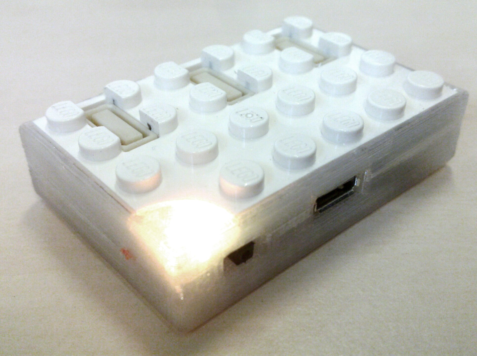
The BRIX₂ Base Module can be turned on using the black switch next to the USB connector. If you have a close look, you will see an O on the left hand side of the switch and a I on the right hand side refering to OFF and ON. However, when it's pushed towards the USB connector, it is ON. This is also indicated by a small green LED that sits right next to the RGB LED and lights up 1 second after the module is turned on.. That indicator LED can be turned off in order to save power, but this is not recommended as you might want to see if the module is running or not.
On startup, the BRIX₂ Base Module is likely to show a 'breathing pattern' 15 times on the blue channel of the RGB LED.
Charging
Charging is as simple as plugging the module into a USB power supply, which can also be a regular USB port. The red charging LED lights up even if the module is turned off. As long as that LED is lit, the module is charging. If the LED turns off, the battery is full. It is recommended to charge the module while it is turned off to minimize the charging time. If the battery is full and the module is running on USB power, it will only use the USB power source and not drain the battery. The full charge time is approximately 1.3 hours.
Handling hints
If in doubt, use common sense!
The microUSB connector is sensitive to mechanical force. Do not apply a lot of mechanical stress to the cable once it is connected, otherwise the connector might rip off the circuitboard. This is an issue with almost all mobile USB devices that use microUSB connectors. Just be careful and use common sense.
The battery of the BRIX₂ Base Module is a LiPoly type which is especially sensitive to punctuation. Never attempt to puncture the BRIX₂ case, because you might hit the battery or the electronics, possibly resulting in a broken/burning/exploding device.
The BRIX₂ Base Module is not waterproof. Under certain circumstances, the red charge LED may emit small amounts of radioactivity.
Absolute Maximum Ratings
The Extension Header allows you to draw power from the BRIX₂ Base Module in two different ways:
- Regulated 3.3V on the VCC pin. You can draw up to 400mA, which also includes other Extension Modules. If you draw more than that, a fuse on the Base Module will blow and have to be replaced. The same thing happens if you short-circuit VCC and GND. Don't do that!
- USB 5.0V on the VUSB pin. Of course this is only available if the Base Module is connected to a USB port or a USB power source. You can draw about as much power as your USB port is able to provide. Everything beyond 1A should be handled with care to not burn the traces on the BRIX₂ circuit board. If you short VUSB and GND, in theory your USB port or power source will shut down. If it does not, you are in trouble!
System Limitations
Microcontroller: The microcontroller is an 8-bit controller with 32 kB flash and 2.5 kB RAM running at 16 MHz. This means your compiled program can only be a little less than 32 kb in size. This sounds very little, but it's sufficient for many applications. But you should be aware of the limitation and optimize your programs towards efficiency.
Battery: The capacity of the battery is about half the capacity of your smartphone battery. But there is no quadcore processor or power hungry wireless connection or massive display installed in a BRIX₂ module, so depending on your application, the module can run quite a long time.
Wireless Transmitter: The range and bandwidth of the transmitter is limited. If the antenna is unfolded, the range is around 30 meters. Increasing packet loss will occur if
- The distance between two communicating modules increases
- Walls weaken the RF signal
- Other nearby devices also use the 868 MHz band
- Many packets are sent in small intervals
- Many modules send packets to a single central module
Sensor: The sensor is capable of measuring linear acceleration up to ±16 g, angular velocity up to ±2000°/sec and magnetic fields in a range of ±1200 μT. The internal motion processing unit (DMP) can calculate a full set of processed data (e.g. Quaternions) 200 times a second.
Sensor
The MPU9150 9-axis motion sensor measures linear acceleration, angular velocity and magnetic fields. (What does that mean?). It is also capable of internally processing that data and provide you the heading (Quaternions, Euler Angles, Roll/Pitch/Yaw) of the device. (What does that mean?)
For hints on reading the sensor data, please have a look at the examples provided or the wiki page about the LiBRIX₂.
RGB LED
The RGB LED allows the BRIX₂ Base Module to talk to you if you are not using a data connection. You can use the LED to debug your code (for example if a loop is entered, the LED turns blue), display data (temperature data changes LED color from blue to red), or to interact with a user. Using the red, green and blue component of the LED, you can generate over 16 million colors.
The RGB LED is wired to three pins of the User Controller:
- Red: 10
- Green: 11
- Blue: 13
You should always use the LiBRIX functions setRGB() or setHSV() to control the LED. You set the LED color by defining the R(ed), G(reen) and B(lue) component of the color, see https://opensource.cit-ec.de/projects/brix2/wiki/LiBRIX₂#System and the example codes:
//////////////////////////////////////////////////////
// BlinkLED,                                        //
// User Application,                                //
// This example demonstrates how to control the LED //
//////////////////////////////////////////////////////

#include <BRIX2.h>

BRIX2 myBrick;

void setup(){
 myBrick.initialize();
}

void loop(){
  // Turn red LED on.
  myBrick.setRGB(255,0,0);
  // wait 500 milliseconds
  delay(500);
  // Turn green LED on.
  myBrick.setRGB(0,255,0);
  delay(500);
  // Turn blue LED on.
  myBrick.setRGB(0,0,255);
  delay(500);
  // turn all LEDs off
  myBrick.setRGB(0,0,0);
  // wait a second
  delay(1000);
  // you can also mix colors
  // yellow:
  myBrick.setRGB(255,255,0);
  delay(1000);
  // pink:
  myBrick.setRGB(255,0,255);
  delay(1000);
  // cyan:
  myBrick.setRGB(0,255,255);
  delay(1000);
  // white:
  myBrick.setRGB(255,255,255);
  delay(1000);
  myBrick.setRGB(0,0,0);
  //here we loop again after a second
  delay(1000);
}
Extension Ports
The BRIX₂ Base Module has 3 Extension Ports on top. These 30-way fine-pitch connectors are internally connected to the User Controller, the power lines and the system controller. In order to connect your custom hardware to an Extension Port, you can use the Breakout Extension Module. All three Extension Ports are 100% parallel, which means it does not matter where you put an Extension Module, it will work the same way. This also means that Extension Modules can influence each other's functionality if they use the same pins on the User Controller, for example. There is a table in BRIX₂ Extension Modules that lists possible conflicts.
Larger image: https://opensource.cit-ec.de/attachments/download/226/pinmapping_scrib.png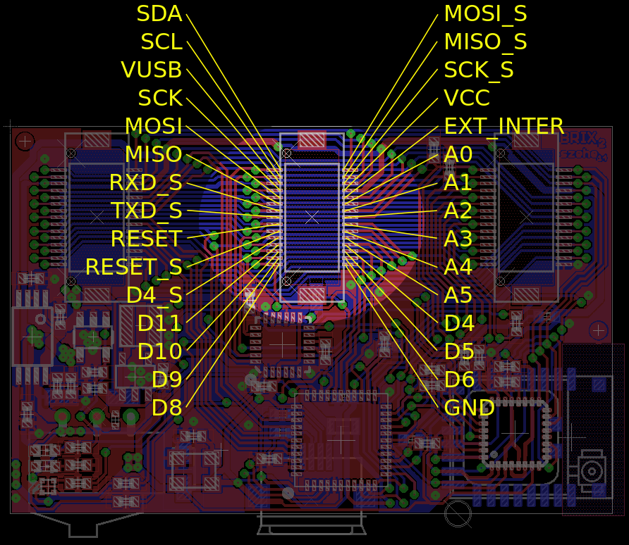
| SDA | I2C data line of User Controller |
| SCL | I2C clock line of User Controller |
| VUSB | 5V DC when USB is connected |
| SCK | SPI clock line of User Controller |
| MOSI | SPI data line of User Controller |
| MISO | SPI data line of User Controller |
| RXD_S | Serial RX of System Controller |
| TXD_S | Serial TX of System Controller |
| RESET | Reset line of User Controller |
| RESET_S | Reset line of System Controller |
| D4_S | Digital pin 4 of System Controller |
| D11 | Digital pin 11 of User Controller |
| D10 | Digital pin 10 of User Controller |
| D9 | Digital pin 9 of User Controller |
| D8 | Digital pin 8 of User Controller |
| GND | System ground |
| D6 | Digital pin 6 of User Controller |
| D5 | Digital pin 5 of User Controller |
| D4 | Digital pin 4 of User Controller |
| A5 | Analog pin 5 of User Controller |
| A4 | Analog pin 4 of User Controller |
| A3 | Analog pin 3 of User Controller |
| A2 | Analog pin 2 of User Controller |
| A1 | Analog pin 1 of User Controller |
| A0 | Analog pin 0 of User Controller |
| EXT_INTER | Interconnects Extension Headers |
| VCC | 3.3V @ 400mA max. |
| SCK_S | SPI clock line of System Controller |
| MISO_S | SPI data line of System Controller |
| MOSI_S | SPI data line of System Controller |
RF Interface
BRIX₂ contains a Texas Instruments CC1101 RF transceiver operating in the 868MHz band. We actually use an Anaren A1101 module that houses that IC. Proprietary RF means that there is no complex protocol layer above the communication. Basically, the chip just sends data bytes over the air to other chips. The LiBRIX2 wraps these functions and allows you to send numbers or text to other BRIX₂ modules.
For more information on how to use the RF interface, check the documentation on the LiBRIX₂