Breakout Extension Module
Type: Connector
Inventory: 16 units
Pins: All optional
Warning: If you use this Extension, you should totally know what you are doing. It is easily possible to temporarily or permanently damage or destroy a BRIX₂ Base Module and/or connected Extension Modules if you screw it up. If in doubt, ask a developer!
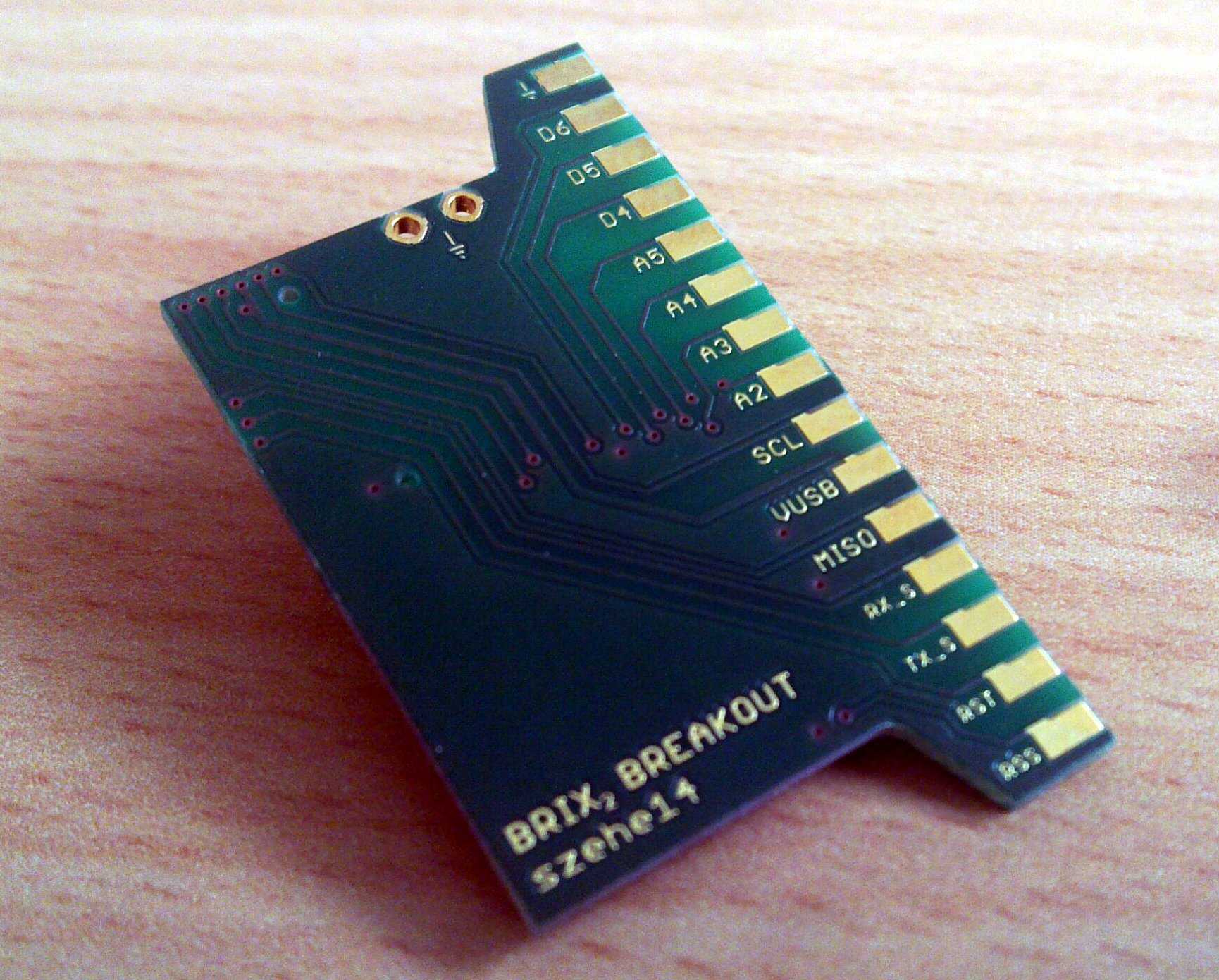
The Breakout Extension Module is intended for prototyping. You want to connect something to a BRIX₂ Base Module that does not exist as an Extension Module yet? Use this module. All pins from the Extension header can be accessed. There are additional ground connections too. You can solder a two-row pinheader to the edge of the board in order to access the pins with a ribbon cable for example.
It is important to consider the power limitations when tinkering with the BRIX₂ Base Module.
Pin Mapping
Developer Informations
Connector Pin Mapping
The table below shows the pin mapping of the DF17 header (On the Base Module), the connecting IDC-30 header on the bottom side of every Extension Module.
| DF-17-30 | IDC-30 | Pin | Description |
| 30 | 1 | GND | System ground |
| 16 | 2 | MOSI_S | SPI data line of System Controller |
| 29 | 3 | D6 | Digital pin 6 of User Controller |
| 17 | 4 | MISO_S | SPI data line of System Controller |
| 28 | 5 | D5 | Digital pin 5 of User Controller |
| 18 | 6 | SCK_S | SPI clock line of System Controller |
| 27 | 7 | D4 | Digital pin 4 of User Controller |
| 19 | 8 | VCC | 3.3V @ 400mA max. |
| 26 | 9 | A5 | Analog pin 5 of User Controller |
| 20 | 10 | EXT_INTER | Interconnects Extension Headers |
| 25 | 11 | A4 | Analog pin 4 of User Controller |
| 21 | 12 | A0 | Analog pin 0 of User Controller |
| 24 | 13 | A3 | Analog pin 3 of User Controller |
| 22 | 14 | A1 | Analog pin 1 of User Controller |
| 23 | 15 | A2 | Analog pin 2 of User Controller |
| 15 | 16 | SDA | I2C data line of User Controller |
| 14 | 17 | SCL | I2C clock line of User Controller |
| 12 | 18 | SCK | SPI clock line of User Controller |
| 13 | 19 | VUSB | 5V DC when USB is connected |
| 11 | 20 | MOSI | SPI data line of User Controller |
| 10 | 21 | MISO | SPI data line of User Controller |
| 1 | 22 | D8 | Digital pin 8 of User Controller |
| 9 | 23 | RXD_S | Serial RX of System Controller |
| 2 | 24 | D9 | Digital pin 9 of User Controller |
| 8 | 25 | TXD_S | Serial TX of System Controller |
| 3 | 26 | D10 | Digital pin 10 of User Controller |
| 7 | 27 | RESET | Reset line of User Controller |
| 4 | 28 | D11 | Digital pin 11 of User Controller |
| 6 | 29 | RESET_S | Reset line of System Controller |
| 5 | 30 | D4_S | Digital pin 4 of System Controller |