BNO Extension Module
Type: Digital Sensor
Measures: Linear Acceleration, Angular Velocity, Magnetic Fields
Inventory: 5 units
Pins: SDA, SCL, optional RX_s, TX_s
This extension is a breakout board for the Bosch Sensortec BNO055 9-axis motion sensor. (Datasheet)
Status: Tested, Working
Jumper Configurations
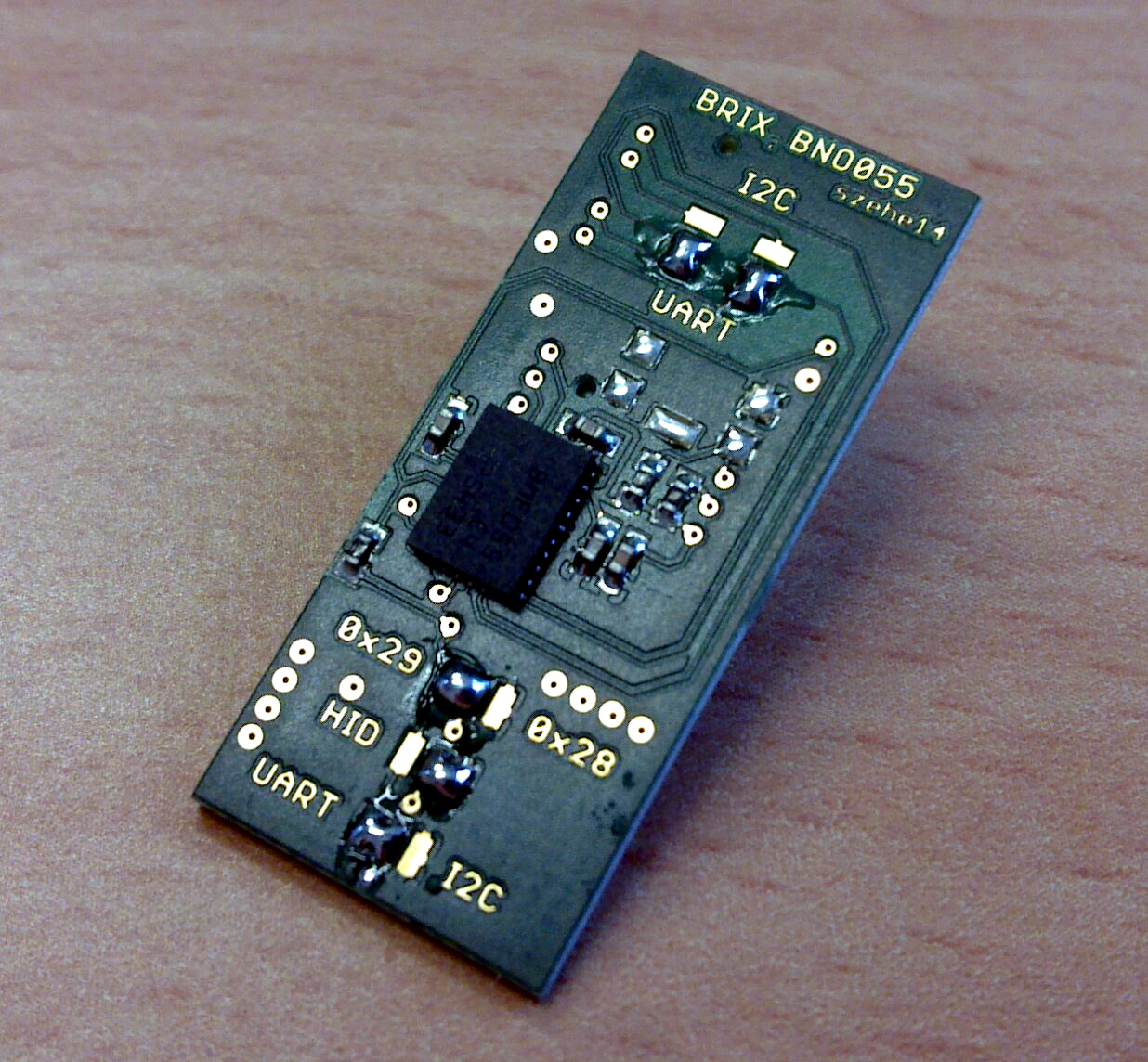
>>> The default configuration is I²C, address 0x29, no HID <<<
There are two banks of jumpers on the top side of the board. (refering to image)
The lower one has three solder jumpers (top to bottom):
- Address Selection
- I²C HID Mode Enable (I²C has to be selected as digital interface)
- Digital Interface Select (UART/I²C)
The upper one patches the digital interface lines to either SCL/SDA (I²C) or RX_s/TX_s (UART). Use these jumpers together with the Digital Interface Select jumper.
Example for UART
Note that the System Controller needs to run an empty sketch for this to work!
(Datasheet, p.104)
Settings:- 115200 bps
- 8 data bits
- no parity bit
- one stop bit)
- The maximum length support for read and write is 128 Byte.
Register Read
| Byte 1 | Byte 2 | Byte 3 | Byte 4 | |
Start Byte | Read | Reg addr | Length |
| 0xAA | 0x01 | <..> | <..> |
Register Write
| Byte 1 | Byte 2 | Byte 3 | Byte 4 | Byte 5 | ... | Data (n+4) |
| Start Byte | Write | Reg addr | Length | Data 1 | ... | Data n |
| 0xAA | 0x00 | <..> | <..> | <..> | ... | <..> |
Success response
| Byte 1 | Byte 2 | Byte 3 | ... | Data (n+2) |
| Response Byte | Length | Data 1 | ... | Data n |
| 0xBB | <..> | <..> | ... | <..> |
Activate sensor fusion:
Write ODR_MODE register (addr: 0x3D)
set fusion mode to "IMU" (p.20) and data rate to "FASTEST_MODE (p. 31)
AA 00 3D 01 18
Get euler angles
(p. 39):
Send:
Response:AA 01 1A 06
| BB | 06 | Heading LSB | Heading MSB | Roll LSB | Roll MSB | Pitch LSB | Pitch MSB |
Get quaternion
(p. 40):
Send:
Response:AA 01 20 08
| BB | 08 | w LSB | w MSB | x LSB | x MSB | y LSB | y MSB | z LSB | z MSB |
Read Quaternions with BRIX₂. Connect RX/TX to TX_S/RX_S:
char getQuaternion[] = {0xAA, 0x01, 0x20, 0x08};
int incomingByte = 0;   // for incoming serial data

void setup(){
  Serial1.begin(115200);
  Serial.begin(115200);
  delay(2000);
  Serial.println("Initializing DMP...");
  initDMP();
  delay(500);
  readResponse();
}

void loop(){
  Serial1.print(getQuaternion);
  delay (10);
  readResponse();
}

void readResponse(){
  byte incoming[10];
  int counter = 0;
  while (Serial1.available() > 0) {
    // read the incoming byte:
    incomingByte = Serial1.read();
    incoming[counter] = incomingByte;
    counter ++;
  }
  // filter too short packages
  if (counter > 9){
    // hex output
    /*
    for (int i = 0;i<10;i++){
      Serial.print("0x");
      Serial.print(incoming[i], HEX);
      Serial.print(" ");
    }
    Serial.println();
    */
    int w = (incoming[3]<<8) + incoming[2];
    int x = (incoming[5]<<8) + incoming[4];
    int y = (incoming[7]<<8) + incoming[6];
    int z = (incoming[9]<<8) + incoming[8];

    float w_f = w/16384.0;
    float x_f = x/16384.0;
    float y_f = y/16384.0;
    float z_f = z/16384.0;

    Serial.print(w_f);
    Serial.print("\t");
    Serial.print(x_f);
    Serial.print("\t");
    Serial.print(y_f);
    Serial.print("\t");
    Serial.println(z_f);
  }
}

// we can not just define this as a string array because
// serial.print will not print 0x00. Therefore we have to
// use serial1.write which does only support single bytes.

void initDMP(){
  Serial1.write(0xAA);
  Serial1.write(0x00);
  Serial1.write(0x3D);
  Serial1.write(0x01);
  Serial1.write(0x18);
}
(Thanks to Marc Hesse)
I²C Example
taken and modified from https://github.com/kriswiner/BNO-055
/* BNO055_MS5637_t3 Basic Example Code
 by: Kris Winer
 date: October 19, 2014
 license: Beerware - Use this code however you'd like. If you
 find it useful you can buy me a beer some time.

 Demonstrates basic BNO055 functionality including parameterizing the register addresses,
 initializing the sensor, communicating with pressure sensor MS5637,
 getting properly scaled accelerometer, gyroscope, and magnetometer data out.

 Added display functions to allow display to on breadboard monitor.

 Addition of 9 DoF sensor fusion using open source Madgwick and Mahony filter algorithms.
 Can compare results to hardware 9 DoF sensor fusion carried out on the BNO055.
 Sketch runs on the 3.3 V 8 MHz Pro Mini and the Teensy 3.1.

 This sketch is intended specifically for the BNO055+MS5637 Add-On Shield for the Teensy 3.1.
 It uses SDA/SCL on pins 17/16, respectively, and it uses the Teensy 3.1-specific Wire library i2c_t3.h.

 The Add-on shield can also be used as a stand-alone breakout board for any Arduino, Teensy, or
 other microcontroller by closing the solder jumpers on the back of the board.

 The MS5637 is a simple but high resolution (24-bit) pressure sensor, which can be used in its high resolution
 mode but with power consumption of 20 microAmp, or in a lower resolution mode with power consumption of
 only 1 microAmp. The choice will depend on the application.

 All sensors communicate via I2C at 400 Hz or higher.
 SDA and SCL should have external pull-up resistors (to 3.3V).
 4K7 resistors are on the BNO055_MS5637 breakout board.

 Hardware setup:
 Breakout Board --------- Arduino/Teensy
 3V3 ---------------------- 3.3V
 SDA -----------------------A4/17
 SCL -----------------------A5/16
 GND ---------------------- GND

 Note: The BNO055_MS5637 breakout board is an I2C sensor and uses the Arduino Wire or Teensy i2c_t3.h library.
 Because the sensor is not 5V tolerant, we are using a 3.3 V 8 MHz Pro Mini or a 3.3 V Teensy 3.1.
 We have disabled the internal pull-ups used by the Wire library in the Wire.h/twi.c utility file.
 We are also using the 400 kHz fast I2C mode by setting the TWI_FREQ  to 400000L /twi.h utility file.
 The Teensy has no internal pullups and we are using the Wire.begin function of the i2c_t3.h library
 to select 400 Hz i2c speed.
 */
#include <Wire.h>

#include <SPI.h>

// BNO055 Register Map
// http://ae-bst.resource.bosch.com/media/products/dokumente/bno055/BST_BNO055_DS000_10_Release.pdf
//
// BNO055 Page 0
#define BNO055_CHIP_ID          0x00    // should be 0xA0
#define BNO055_ACC_ID           0x01    // should be 0xFB
#define BNO055_MAG_ID           0x02    // should be 0x32
#define BNO055_GYRO_ID          0x03    // should be 0x0F
#define BNO055_SW_REV_ID_LSB    0x04
#define BNO055_SW_REV_ID_MSB    0x05
#define BNO055_BL_REV_ID        0x06
#define BNO055_PAGE_ID          0x07
#define BNO055_ACC_DATA_X_LSB   0x08
#define BNO055_ACC_DATA_X_MSB   0x09
#define BNO055_ACC_DATA_Y_LSB   0x0A
#define BNO055_ACC_DATA_Y_MSB   0x0B
#define BNO055_ACC_DATA_Z_LSB   0x0C
#define BNO055_ACC_DATA_Z_MSB   0x0D
#define BNO055_MAG_DATA_X_LSB   0x0E
#define BNO055_MAG_DATA_X_MSB   0x0F
#define BNO055_MAG_DATA_Y_LSB   0x10
#define BNO055_MAG_DATA_Y_MSB   0x11
#define BNO055_MAG_DATA_Z_LSB   0x12
#define BNO055_MAG_DATA_Z_MSB   0x13
#define BNO055_GYR_DATA_X_LSB   0x14
#define BNO055_GYR_DATA_X_MSB   0x15
#define BNO055_GYR_DATA_Y_LSB   0x16
#define BNO055_GYR_DATA_Y_MSB   0x17
#define BNO055_GYR_DATA_Z_LSB   0x18
#define BNO055_GYR_DATA_Z_MSB   0x19
#define BNO055_EUL_HEADING_LSB  0x1A
#define BNO055_EUL_HEADING_MSB  0x1B
#define BNO055_EUL_ROLL_LSB     0x1C
#define BNO055_EUL_ROLL_MSB     0x1D
#define BNO055_EUL_PITCH_LSB    0x1E
#define BNO055_EUL_PITCH_MSB    0x1F
#define BNO055_QUA_DATA_W_LSB   0x20
#define BNO055_QUA_DATA_W_MSB   0x21
#define BNO055_QUA_DATA_X_LSB   0x22
#define BNO055_QUA_DATA_X_MSB   0x23
#define BNO055_QUA_DATA_Y_LSB   0x24
#define BNO055_QUA_DATA_Y_MSB   0x25
#define BNO055_QUA_DATA_Z_LSB   0x26
#define BNO055_QUA_DATA_Z_MSB   0x27
#define BNO055_LIA_DATA_X_LSB   0x28
#define BNO055_LIA_DATA_X_MSB   0x29
#define BNO055_LIA_DATA_Y_LSB   0x2A
#define BNO055_LIA_DATA_Y_MSB   0x2B
#define BNO055_LIA_DATA_Z_LSB   0x2C
#define BNO055_LIA_DATA_Z_MSB   0x2D
#define BNO055_GRV_DATA_X_LSB   0x2E
#define BNO055_GRV_DATA_X_MSB   0x2F
#define BNO055_GRV_DATA_Y_LSB   0x30
#define BNO055_GRV_DATA_Y_MSB   0x31
#define BNO055_GRV_DATA_Z_LSB   0x32
#define BNO055_GRV_DATA_Z_MSB   0x33
#define BNO055_TEMP             0x34
#define BNO055_CALIB_STAT       0x35
#define BNO055_ST_RESULT        0x36
#define BNO055_INT_STATUS       0x37
#define BNO055_SYS_CLK_STATUS   0x38
#define BNO055_SYS_STATUS       0x39
#define BNO055_SYS_ERR          0x3A
#define BNO055_UNIT_SEL         0x3B
#define BNO055_OPR_MODE         0x3D
#define BNO055_PWR_MODE         0x3E
#define BNO055_SYS_TRIGGER      0x3F
#define BNO055_TEMP_SOURCE      0x40
#define BNO055_AXIS_MAP_CONFIG  0x41
#define BNO055_AXIS_MAP_SIGN    0x42
#define BNO055_ACC_OFFSET_X_LSB 0x55
#define BNO055_ACC_OFFSET_X_MSB 0x56
#define BNO055_ACC_OFFSET_Y_LSB 0x57
#define BNO055_ACC_OFFSET_Y_MSB 0x58
#define BNO055_ACC_OFFSET_Z_LSB 0x59
#define BNO055_ACC_OFFSET_Z_MSB 0x5A
#define BNO055_MAG_OFFSET_X_LSB 0x5B
#define BNO055_MAG_OFFSET_X_MSB 0x5C
#define BNO055_MAG_OFFSET_Y_LSB 0x5D
#define BNO055_MAG_OFFSET_Y_MSB 0x5E
#define BNO055_MAG_OFFSET_Z_LSB 0x5F
#define BNO055_MAG_OFFSET_Z_MSB 0x60
#define BNO055_GYR_OFFSET_X_LSB 0x61
#define BNO055_GYR_OFFSET_X_MSB 0x62
#define BNO055_GYR_OFFSET_Y_LSB 0x63
#define BNO055_GYR_OFFSET_Y_MSB 0x64
#define BNO055_GYR_OFFSET_Z_LSB 0x65
#define BNO055_GYR_OFFSET_Z_MSB 0x66
#define BNO055_ACC_RADIUS_LSB   0x67
#define BNO055_ACC_RADIUS_MSB   0x68
#define BNO055_MAG_RADIUS_LSB   0x69
#define BNO055_MAG_RADIUS_MSB   0x6A
//
// BNO055 Page 1
#define BNO055_PAGE_ID          0x07
#define BNO055_ACC_CONFIG       0x08
#define BNO055_MAG_CONFIG       0x09
#define BNO055_GYRO_CONFIG_0    0x0A
#define BNO055_GYRO_CONFIG_1    0x0B
#define BNO055_ACC_SLEEP_CONFIG 0x0C
#define BNO055_GYR_SLEEP_CONFIG 0x0D
#define BNO055_INT_MSK          0x0F
#define BNO055_INT_EN           0x10
#define BNO055_ACC_AM_THRES     0x11
#define BNO055_ACC_INT_SETTINGS 0x12
#define BNO055_ACC_HG_DURATION  0x13
#define BNO055_ACC_HG_THRESH    0x14
#define BNO055_ACC_NM_THRESH    0x15
#define BNO055_ACC_NM_SET       0x16
#define BNO055_GYR_INT_SETTINGS 0x17
#define BNO055_GYR_HR_X_SET     0x18
#define BNO055_GYR_DUR_X        0x19
#define BNO055_GYR_HR_Y_SET     0x1A
#define BNO055_GYR_DUR_Y        0x1B
#define BNO055_GYR_HR_Z_SET     0x1C
#define BNO055_GYR_DUR_Z        0x1D
#define BNO055_GYR_AM_THRESH    0x1E
#define BNO055_GYR_AM_SET       0x1F

// Using the BNO055_MS5637 breakout board/Teensy 3.1 Add-On Shield, ADO is set to 1 by default
#define ADO 1
#if ADO
#define BNO055_ADDRESS 0x29   //  Device address of BNO055 when ADO = 1
#define MS5637_ADDRESS   0x76   //  Address of MS5637 altimeter
#else
#define BNO055_ADDRESS 0x28   //  Device address of BNO055 when ADO = 0
#define MS5637_ADDRESS   0x76   //  Address of MS5637 altimeter
#endif

#define SerialDebug true      // set to true to get Serial output for debugging

// Set initial input parameters
enum Ascale {  // ACC Full Scale
  AFS_2G = 0,
  AFS_4G,
  AFS_8G,
  AFS_18G
};

enum Abw { // ACC Bandwidth
  ABW_7_81Hz = 0,
  ABW_15_63Hz,
  ABW_31_25Hz,
  ABW_62_5Hz,
  ABW_125Hz,
  ABW_250Hz,
  ABW_500Hz,
  ABW_1000Hz,    //0x07
};

enum APwrMode { // ACC Pwr Mode
  NormalA = 0,
  SuspendA,
  LowPower1A,
  StandbyA,
  LowPower2A,
  DeepSuspendA
};

enum Gscale {  // gyro full scale
  GFS_2000DPS = 0,
  GFS_1000DPS,
  GFS_500DPS,
  GFS_250DPS,
  GFS_125DPS    // 0x04
};

enum GPwrMode { // GYR Pwr Mode
  NormalG = 0,
  FastPowerUpG,
  DeepSuspendedG,
  SuspendG,
  AdvancedPowerSaveG
};

enum Gbw { // gyro bandwidth
  GBW_523Hz = 0,
  GBW_230Hz,
  GBW_116Hz,
  GBW_47Hz,
  GBW_23Hz,
  GBW_12Hz,
  GBW_64Hz,
  GBW_32Hz
};

enum OPRMode {  // BNO-55 operation modes
  CONFIGMODE = 0x00,
// Sensor Mode
  ACCONLY,
  MAGONLY,
  GYROONLY,
  ACCMAG,
  ACCGYRO,
  MAGGYRO,
  AMG,            // 0x07
// Fusion Mode
  IMU,
  COMPASS,
  M4G,
  NDOF_FMC_OFF,
  NDOF            // 0x0C
};

enum PWRMode {
  Normalpwr = 0,
  Lowpower,
  Suspendpwr
};

enum Modr {         // magnetometer output data rate
  MODR_2Hz = 0,
  MODR_6Hz,
  MODR_8Hz,
  MODR_10Hz,
  MODR_15Hz,
  MODR_20Hz,
  MODR_25Hz,
  MODR_30Hz
};

enum MOpMode { // MAG Op Mode
  LowPower = 0,
  Regular,
  EnhancedRegular,
  HighAccuracy
};

enum MPwrMode { // MAG power mode
  Normal = 0,
  Sleep,
  Suspend,
  ForceMode
};

#define ADC_256  0x00 // define pressure and temperature conversion rates
#define ADC_512  0x02
#define ADC_1024 0x04
#define ADC_2048 0x06
#define ADC_4096 0x08
#define ADC_8192 0x0A
#define ADC_D1   0x40
#define ADC_D2   0x50

// Specify sensor configuration
uint8_t OSR = ADC_8192;       // set pressure amd temperature oversample rate
//
uint8_t GPwrMode = Normal;    // Gyro power mode
uint8_t Gscale = GFS_250DPS;  // Gyro full scale
//uint8_t Godr = GODR_250Hz;    // Gyro sample rate
uint8_t Gbw = GBW_23Hz;       // Gyro bandwidth
//
uint8_t Ascale = AFS_2G;      // Accel full scale
//uint8_t Aodr = AODR_250Hz;    // Accel sample rate
uint8_t APwrMode = Normal;    // Accel power mode
uint8_t Abw = ABW_31_25Hz;    // Accel bandwidth, accel sample rate divided by ABW_divx
//
//uint8_t Mscale = MFS_4Gauss;  // Select magnetometer full-scale resolution
uint8_t MOpMode = HighAccuracy;    // Select magnetometer perfomance mode
uint8_t MPwrMode = Normal;    // Select magnetometer power mode
uint8_t Modr = MODR_10Hz;     // Select magnetometer ODR when in BNO055 bypass mode

uint8_t PWRMode = Normal ;    // Select BNO055 power mode
uint8_t OPRMode = NDOF;        // specify operation mode for sensors
uint8_t status;               // BNO055 data status register
float aRes, gRes, mRes;       // scale resolutions per LSB for the sensors

// Pin definitions
int intPin = 8;  // These can be changed, 2 and 3 are the Arduinos ext int pins
int myLed = 13;

uint16_t Pcal[8];         // calibration constants from MS5637 PROM registers
unsigned char nCRC;       // calculated check sum to ensure PROM integrity
uint32_t D1 = 0, D2 = 0;  // raw MS5637 pressure and temperature data
double dT, OFFSET, SENS, T2, OFFSET2, SENS2;  // First order and second order corrections for raw S5637 temperature and pressure data
int16_t accelCount[3];  // Stores the 16-bit signed accelerometer sensor output
int16_t gyroCount[3];   // Stores the 16-bit signed gyro sensor output
int16_t magCount[3];    // Stores the 16-bit signed magnetometer sensor output
int16_t quatCount[4];   // Stores the 16-bit signed quaternion output
int16_t EulCount[3];    // Stores the 16-bit signed Euler angle output
int16_t LIACount[3];    // Stores the 16-bit signed linear acceleration output
int16_t GRVCount[3];    // Stores the 16-bit signed gravity vector output
float gyroBias[3] = {0, 0, 0}, accelBias[3] = {0, 0, 0}, magBias[3] = {0, 0, 0};  // Bias corrections for gyro, accelerometer, and magnetometer
int16_t tempGCount, tempMCount;      // temperature raw count output of mag and gyro
float   Gtemperature, Mtemperature;  // Stores the BNO055 gyro and LIS3MDL mag internal chip temperatures in degrees Celsius
double Temperature, Pressure;        // stores MS5637 pressures sensor pressure and temperature

// global constants for 9 DoF fusion and AHRS (Attitude and Heading Reference System)
float GyroMeasError = PI * (40.0f / 180.0f);   // gyroscope measurement error in rads/s (start at 40 deg/s)
float GyroMeasDrift = PI * (0.0f  / 180.0f);   // gyroscope measurement drift in rad/s/s (start at 0.0 deg/s/s)
// There is a tradeoff in the beta parameter between accuracy and response speed.
// In the original Madgwick study, beta of 0.041 (corresponding to GyroMeasError of 2.7 degrees/s) was found to give optimal accuracy.
// However, with this value, the LSM9SD0 response time is about 10 seconds to a stable initial quaternion.
// Subsequent changes also require a longish lag time to a stable output, not fast enough for a quadcopter or robot car!
// By increasing beta (GyroMeasError) by about a factor of fifteen, the response time constant is reduced to ~2 sec
// I haven't noticed any reduction in solution accuracy. This is essentially the I coefficient in a PID control sense;
// the bigger the feedback coefficient, the faster the solution converges, usually at the expense of accuracy.
// In any case, this is the free parameter in the Madgwick filtering and fusion scheme.
float beta = sqrt(3.0f / 4.0f) * GyroMeasError;   // compute beta
float zeta = sqrt(3.0f / 4.0f) * GyroMeasDrift;   // compute zeta, the other free parameter in the Madgwick scheme usually set to a small or zero value
#define Kp 2.0f * 5.0f // these are the free parameters in the Mahony filter and fusion scheme, Kp for proportional feedback, Ki for integral
#define Ki 0.0f

uint32_t delt_t = 0, count = 0, sumCount = 0;  // used to control display output rate
float pitch, yaw, roll;
float Pitch, Yaw, Roll;
float LIAx, LIAy, LIAz, GRVx, GRVy, GRVz;
float deltat = 0.0f, sum = 0.0f;          // integration interval for both filter schemes
uint32_t lastUpdate = 0, firstUpdate = 0; // used to calculate integration interval
uint32_t Now = 0;                         // used to calculate integration interval

float ax, ay, az, gx, gy, gz, mx, my, mz; // variables to hold latest sensor data values
float q[4] = {1.0f, 0.0f, 0.0f, 0.0f};    // vector to hold quaternion
float quat[4] = {1.0f, 0.0f, 0.0f, 0.0f};    // vector to hold quaternion
float eInt[3] = {0.0f, 0.0f, 0.0f};       // vector to hold integral error for Mahony method

void setup()
{
//  Wire.begin();
//  TWBR = 12;  // 400 kbit/sec I2C speed for Pro Mini
  // Setup for Master mode, pins 16/17, external pullups, 400kHz for Teensy 3.1
  Wire.begin();
  delay(4000);
  Serial.begin(38400);

  // Set up the interrupt pin, its set as active high, push-pull
  pinMode(intPin, INPUT);
  pinMode(myLed, OUTPUT);
  digitalWrite(myLed, HIGH);

/*
// scan for i2c devices
  byte error, address;
  int nDevices;

  Serial.println("Scanning...");

  nDevices = 0;
  for(address = 1; address < 127; address++ )
  {
    // The i2c_scanner uses the return value of
    // the Write.endTransmisstion to see if
    // a device did acknowledge to the address.
    Wire.beginTransmission(address);
    error = Wire.endTransmission();

    if (error == 0)
    {
      Serial.print("I2C device found at address 0x");
      if (address<16)
        Serial.print("0");
      Serial.print(address,HEX);
      Serial.println("  !");

      nDevices++;
    }
    else if (error==4)
    {
      Serial.print("Unknow error at address 0x");
      if (address<16)
        Serial.print("0");
      Serial.println(address,HEX);
    }
  }
  if (nDevices == 0)
    Serial.println("No I2C devices found\n");
  else
    Serial.println("done\n");

  */

  // Read the WHO_AM_I register, this is a good test of communication
  Serial.println("BNO055 9-axis motion sensor...");
  byte c = readByte(BNO055_ADDRESS, BNO055_CHIP_ID);  // Read WHO_AM_I register for BNO055
  Serial.print("BNO055 Address = 0x"); Serial.println(BNO055_ADDRESS, HEX);
  Serial.print("BNO055 WHO_AM_I = 0x"); Serial.println(BNO055_CHIP_ID, HEX);
  Serial.print("BNO055 "); Serial.print("I AM "); Serial.print(c, HEX); Serial.println(" I should be 0xA0");

  delay(1000);

    // Read the WHO_AM_I register of the accelerometer, this is a good test of communication
  byte d = readByte(BNO055_ADDRESS, BNO055_ACC_ID);  // Read WHO_AM_I register for accelerometer
  Serial.print("BNO055 ACC "); Serial.print("I AM "); Serial.print(d, HEX); Serial.println(" I should be 0xFB");

  delay(1000);

  // Read the WHO_AM_I register of the magnetometer, this is a good test of communication
  byte e = readByte(BNO055_ADDRESS, BNO055_MAG_ID);  // Read WHO_AM_I register for magnetometer
  Serial.print("BNO055 MAG "); Serial.print("I AM "); Serial.print(e, HEX); Serial.println(" I should be 0x32");

  delay(1000);

  // Read the WHO_AM_I register of the gyroscope, this is a good test of communication
  byte f = readByte(BNO055_ADDRESS, BNO055_GYRO_ID);  // Read WHO_AM_I register for LIS3MDL
  Serial.print("BNO055 GYRO "); Serial.print("I AM "); Serial.print(f, HEX); Serial.println(" I should be 0x0F");

  delay(1000);

  if (c == 0xA0) // BNO055 WHO_AM_I should always be 0xA0
  {
    Serial.println("BNO055 is online...");

    // Check software revision ID
    byte swlsb = readByte(BNO055_ADDRESS, BNO055_SW_REV_ID_LSB);
    byte swmsb = readByte(BNO055_ADDRESS, BNO055_SW_REV_ID_MSB);
    Serial.print("BNO055 SW Revision ID: "); Serial.print(swmsb, HEX); Serial.print("."); Serial.println(swlsb, HEX);
    Serial.println("Should be 03.04");

    // Check bootloader version
    byte blid = readByte(BNO055_ADDRESS, BNO055_BL_REV_ID);
    Serial.print("BNO055 bootloader Version: "); Serial.println(blid);

    // Check self-test results
    byte selftest = readByte(BNO055_ADDRESS, BNO055_ST_RESULT);

    if(selftest & 0x01) {
      Serial.println("accelerometer passed selftest");
    } else {
      Serial.println("accelerometer failed selftest");
    }
    if(selftest & 0x02) {
      Serial.println("magnetometer passed selftest");
    } else {
      Serial.println("magnetometer failed selftest");
    }
    if(selftest & 0x04) {
      Serial.println("gyroscope passed selftest");
    } else {
      Serial.println("gyroscope failed selftest");
    }
    if(selftest & 0x08) {
      Serial.println("MCU passed selftest");
    } else {
      Serial.println("MCU failed selftest");
    }

    delay(1000);

  delay(1000);

  accelgyroCalBNO055(accelBias, gyroBias);

  Serial.println("Average accelerometer bias (mg) = "); Serial.println(accelBias[0]); Serial.println(accelBias[1]); Serial.println(accelBias[2]);
  Serial.println("Average gyro bias (dps) = "); Serial.println(gyroBias[0]); Serial.println(gyroBias[1]); Serial.println(gyroBias[2]);

  delay(1000);

  magCalBNO055(magBias);

  Serial.println("Average magnetometer bias (mG) = "); Serial.println(magBias[0]); Serial.println(magBias[1]); Serial.println(magBias[2]);

  delay(1000);

  // Check calibration status of the sensors
  uint8_t calstat = readByte(BNO055_ADDRESS, BNO055_CALIB_STAT);
  Serial.println("Not calibrated = 0, fully calibrated = 3");
  Serial.print("System calibration status "); Serial.println( (0xC0 & calstat) >> 6);
  Serial.print("Gyro   calibration status "); Serial.println( (0x30 & calstat) >> 4);
  Serial.print("Accel  calibration status "); Serial.println( (0x0C & calstat) >> 2);
  Serial.print("Mag    calibration status "); Serial.println( (0x03 & calstat) >> 0);

  initBNO055(); // Initialize the BNO055
  Serial.println("BNO055 initialized for sensor mode...."); // Initialize BNO055 for sensor read

  }
  else
  {
    Serial.print("Could not connect to BNO055: 0x");
    Serial.println(c, HEX);
    while(1) ; // Loop forever if communication doesn't happen
  }
}

void loop()
{

    readAccelData(accelCount);  // Read the x/y/z adc values
    // Now we'll calculate the accleration value into actual mg's
    ax = (float)accelCount[0] - accelBias[0];  // subtract off calculated accel bias
    ay = (float)accelCount[1] - accelBias[1];
    az = (float)accelCount[2] - accelBias[2];

    readGyroData(gyroCount);  // Read the x/y/z adc values
    // Calculate the gyro value into actual degrees per second
    gx = (float)gyroCount[0]/16. - gyroBias[0];  // subtract off calculated gyro bias
    gy = (float)gyroCount[1]/16. - gyroBias[1];
    gz = (float)gyroCount[2]/16. - gyroBias[2];

    readMagData(magCount);  // Read the x/y/z adc values
    // Calculate the magnetometer values in milliGauss
    mx = (float)magCount[0]/1.6 - magBias[0];  // get actual magnetometer value in mGauss
    my = (float)magCount[1]/1.6 - magBias[1];
    mz = (float)magCount[2]/1.6 - magBias[2];

    readQuatData(quatCount);  // Read the x/y/z adc values
    // Calculate the quaternion values
    quat[0] = (float)(quatCount[0])/16384.;
    quat[1] = (float)(quatCount[1])/16384.;
    quat[2] = (float)(quatCount[2])/16384.;
    quat[3] = (float)(quatCount[3])/16384.;

    readEulData(EulCount);  // Read the x/y/z adc values
    // Calculate the Euler angles values in degrees
    Yaw = (float)EulCount[0]/16.;
    Roll = (float)EulCount[1]/16.;
    Pitch = (float)EulCount[2]/16.;

    readLIAData(LIACount);  // Read the x/y/z adc values
    // Calculate the linear acceleration (sans gravity) values in mg
    LIAx = (float)LIACount[0];
    LIAy = (float)LIACount[1];
    LIAz = (float)LIACount[2];

    readGRVData(GRVCount);  // Read the x/y/z adc values
    // Calculate the linear acceleration (sans gravity) values in mg
    GRVx = (float)GRVCount[0];
    GRVy = (float)GRVCount[1];
    GRVz = (float)GRVCount[2];

  Now = micros();
  deltat = ((Now - lastUpdate)/1000000.0f); // set integration time by time elapsed since last filter update
  lastUpdate = Now;

  sum += deltat; // sum for averaging filter update rate
  sumCount++;

  // Sensors x, y, and z-axes  for the three sensor: accel, gyro, and magnetometer are all aligned, so
  // no allowance for any orientation mismatch in feeding the output to the quaternion filter is required.
  // For the BNO055, the sensor forward is along the x-axis just like
  // in the LSM9DS0 and MPU9250 sensors. This rotation can be modified to allow any convenient orientation convention.
  // This is ok by aircraft orientation standards!
  // Pass gyro rate as rad/s
 // MadgwickQuaternionUpdate(ax, ay, az, gx*PI/180.0f, gy*PI/180.0f, gz*PI/180.0f,  mx,  my,  mz);
//  MahonyQuaternionUpdate(ax, ay, az, gx*PI/180.0f, gy*PI/180.0f, gz*PI/180.0f, mx, my, mz);

    // Serial print and/or display at 0.5 s rate independent of data rates
    delt_t = millis() - count;
    if (delt_t > 500) { // update LCD once per half-second independent of read rate

       // check BNO-055 error status at 2 Hz rate
    uint8_t errstat = readByte(BNO055_ADDRESS, BNO055_CALIB_STAT);
    if(errstat == 0x01) {
      uint8_t syserr = readByte(BNO055_ADDRESS, BNO055_SYS_ERR);
      if(syserr == 0x01) Serial.println("Peripheral initialization error");
      if(syserr == 0x02) Serial.println("System initialization error");
      if(syserr == 0x03) Serial.println("Self test result failed");
      if(syserr == 0x04) Serial.println("Register map value out of range");
      if(syserr == 0x05) Serial.println("Register map address out of range");
      if(syserr == 0x06) Serial.println("Register map write error");
      if(syserr == 0x07) Serial.println("BNO low power mode no available for selected operation mode");
      if(syserr == 0x08) Serial.println("Accelerometer power mode not available");
      if(syserr == 0x09) Serial.println("Fusion algorithm configuration error");
      if(syserr == 0x0A) Serial.println("Sensor configuration error");
    }

    Serial.print("ax = "); Serial.print((int)ax);
    Serial.print(" ay = "); Serial.print((int)ay);
    Serial.print(" az = "); Serial.print((int)az); Serial.println(" mg");
    Serial.print("gx = "); Serial.print( gx, 2);
    Serial.print(" gy = "); Serial.print( gy, 2);
    Serial.print(" gz = "); Serial.print( gz, 2); Serial.println(" deg/s");
    Serial.print("mx = "); Serial.print( (int)mx );
    Serial.print(" my = "); Serial.print( (int)my );
    Serial.print(" mz = "); Serial.print( (int)mz ); Serial.println(" mG");

    Serial.print("qx = "); Serial.print(q[0]);
    Serial.print(" qy = "); Serial.print(q[1]);
    Serial.print(" qz = "); Serial.print(q[2]);
    Serial.print(" qw = "); Serial.println(q[3]);
    Serial.print("quatw = "); Serial.print(quat[0]);
    Serial.print(" quatx = "); Serial.print(quat[1]);
    Serial.print(" quaty = "); Serial.print(quat[2]);
    Serial.print(" quatz = "); Serial.println(quat[3]);

    tempGCount = readGyroTempData();  // Read the gyro adc values
    Gtemperature = (float) tempGCount; // Gyro chip temperature in degrees Centigrade
   // Print gyro die temperature in degrees Centigrade
    Serial.print("Gyro temperature is ");  Serial.print(Gtemperature, 1);  Serial.println(" degrees C"); // Print T values to tenths of a degree C

  // Define output variables from updated quaternion---these are Tait-Bryan angles, commonly used in aircraft orientation.
  // In this coordinate system, the positive z-axis is down toward Earth.
  // Yaw is the angle between Sensor x-axis and Earth magnetic North (or true North if corrected for local declination, looking down on the sensor positive yaw is counterclockwise.
  // Pitch is angle between sensor x-axis and Earth ground plane, toward the Earth is positive, up toward the sky is negative.
  // Roll is angle between sensor y-axis and Earth ground plane, y-axis up is positive roll.
  // These arise from the definition of the homogeneous rotation matrix constructed from quaternions.
  // Tait-Bryan angles as well as Euler angles are non-commutative; that is, the get the correct orientation the rotations must be
  // applied in the correct order which for this configuration is yaw, pitch, and then roll.
  // For more see http://en.wikipedia.org/wiki/Conversion_between_quaternions_and_Euler_angles which has additional links.
    yaw   = atan2(2.0f * (q[1] * q[2] + q[0] * q[3]), q[0] * q[0] + q[1] * q[1] - q[2] * q[2] - q[3] * q[3]);
    pitch = -asin(2.0f * (q[1] * q[3] - q[0] * q[2]));
    roll  = atan2(2.0f * (q[0] * q[1] + q[2] * q[3]), q[0] * q[0] - q[1] * q[1] - q[2] * q[2] + q[3] * q[3]);
    pitch *= 180.0f / PI;
    yaw   *= 180.0f / PI;
 //   yaw   -= 13.8f; // Declination at Danville, California is 13 degrees 48 minutes and 47 seconds on 2014-04-04
    roll  *= 180.0f / PI;

    Serial.print("Software Yaw, Pitch, Roll: ");
    Serial.print(yaw, 2);
    Serial.print(", ");
    Serial.print(pitch, 2);
    Serial.print(", ");
    Serial.println(roll, 2);

    Serial.print("Hardware Yaw, Pitch, Roll: ");
    Serial.print(Yaw, 2);
    Serial.print(", ");
    Serial.print(Pitch, 2);
    Serial.print(", ");
    Serial.println(Roll, 2);

    Serial.print("Hardware x, y, z linear acceleration: ");
    Serial.print(LIAx, 2);
    Serial.print(", ");
    Serial.print(LIAy, 2);
    Serial.print(", ");
    Serial.println(LIAz, 2);

    Serial.print("Hardware x, y, z gravity vector: ");
    Serial.print(GRVx, 2);
    Serial.print(", ");
    Serial.print(GRVy, 2);
    Serial.print(", ");
    Serial.println(GRVz, 2);

    Serial.print("rate = "); Serial.print((float)sumCount/sum, 2); Serial.println(" Hz");

    digitalWrite(myLed, !digitalRead(myLed));
    count = millis();
    sumCount = 0;
    sum = 0;
    }

}

//===================================================================================================================
//====== Set of useful function to access acceleration. gyroscope, magnetometer, and temperature data
//===================================================================================================================

void readAccelData(int16_t * destination)
{
  uint8_t rawData[6];  // x/y/z accel register data stored here
  readBytes(BNO055_ADDRESS, BNO055_ACC_DATA_X_LSB, 6, &rawData[0]);  // Read the six raw data registers into data array
  destination[0] = ((int16_t)rawData[1] << 8) | rawData[0] ;      // Turn the MSB and LSB into a signed 16-bit value
  destination[1] = ((int16_t)rawData[3] << 8) | rawData[2] ;
  destination[2] = ((int16_t)rawData[5] << 8) | rawData[4] ;
}

void readGyroData(int16_t * destination)
{
  uint8_t rawData[6];  // x/y/z gyro register data stored here
  readBytes(BNO055_ADDRESS, BNO055_GYR_DATA_X_LSB, 6, &rawData[0]);  // Read the six raw data registers sequentially into data array
  destination[0] = ((int16_t)rawData[1] << 8) | rawData[0] ;       // Turn the MSB and LSB into a signed 16-bit value
  destination[1] = ((int16_t)rawData[3] << 8) | rawData[2] ;
  destination[2] = ((int16_t)rawData[5] << 8) | rawData[4] ;
}

int8_t readGyroTempData()
{
  return readByte(BNO055_ADDRESS, BNO055_TEMP);  // Read the two raw data registers sequentially into data array
}

void readMagData(int16_t * destination)
{
  uint8_t rawData[6];  // x/y/z gyro register data stored here
  readBytes(BNO055_ADDRESS, BNO055_MAG_DATA_X_LSB, 6, &rawData[0]);  // Read the six raw data registers sequentially into data array
  destination[0] = ((int16_t)rawData[1] << 8) | rawData[0] ;       // Turn the MSB and LSB into a signed 16-bit value
  destination[1] = ((int16_t)rawData[3] << 8) | rawData[2] ;
  destination[2] = ((int16_t)rawData[5] << 8) | rawData[4] ;
}

void readQuatData(int16_t * destination)
{
  uint8_t rawData[8];  // x/y/z gyro register data stored here
  readBytes(BNO055_ADDRESS, BNO055_QUA_DATA_W_LSB, 8, &rawData[0]);  // Read the six raw data registers sequentially into data array
  destination[0] = ((int16_t)rawData[1] << 8) | rawData[0] ;       // Turn the MSB and LSB into a signed 16-bit value
  destination[1] = ((int16_t)rawData[3] << 8) | rawData[2] ;
  destination[2] = ((int16_t)rawData[5] << 8) | rawData[4] ;
  destination[3] = ((int16_t)rawData[7] << 8) | rawData[6] ;
}

void readEulData(int16_t * destination)
{
  uint8_t rawData[6];  // x/y/z gyro register data stored here
  readBytes(BNO055_ADDRESS, BNO055_EUL_HEADING_LSB, 6, &rawData[0]);  // Read the six raw data registers sequentially into data array
  destination[0] = ((int16_t)rawData[1] << 8) | rawData[0] ;       // Turn the MSB and LSB into a signed 16-bit value
  destination[1] = ((int16_t)rawData[3] << 8) | rawData[2] ;
  destination[2] = ((int16_t)rawData[5] << 8) | rawData[4] ;
}

void readLIAData(int16_t * destination)
{
  uint8_t rawData[6];  // x/y/z gyro register data stored here
  readBytes(BNO055_ADDRESS, BNO055_LIA_DATA_X_LSB, 6, &rawData[0]);  // Read the six raw data registers sequentially into data array
  destination[0] = ((int16_t)rawData[1] << 8) | rawData[0] ;       // Turn the MSB and LSB into a signed 16-bit value
  destination[1] = ((int16_t)rawData[3] << 8) | rawData[2] ;
  destination[2] = ((int16_t)rawData[5] << 8) | rawData[4] ;
}

void readGRVData(int16_t * destination)
{
  uint8_t rawData[6];  // x/y/z gyro register data stored here
  readBytes(BNO055_ADDRESS, BNO055_GRV_DATA_X_LSB, 6, &rawData[0]);  // Read the six raw data registers sequentially into data array
  destination[0] = ((int16_t)rawData[1] << 8) | rawData[0] ;       // Turn the MSB and LSB into a signed 16-bit value
  destination[1] = ((int16_t)rawData[3] << 8) | rawData[2] ;
  destination[2] = ((int16_t)rawData[5] << 8) | rawData[4] ;
}

void initBNO055() {
   // Select page 1 to configure sensors
   writeByte(BNO055_ADDRESS, BNO055_PAGE_ID, 0x01);
   // Configure ACC
   writeByte(BNO055_ADDRESS, BNO055_ACC_CONFIG, APwrMode << 5 | Abw << 3 | Ascale );
   // Configure GYR
   writeByte(BNO055_ADDRESS, BNO055_GYRO_CONFIG_0, Gbw << 3 | Gscale );
   writeByte(BNO055_ADDRESS, BNO055_GYRO_CONFIG_1, GPwrMode);
   // Configure MAG
   writeByte(BNO055_ADDRESS, BNO055_MAG_CONFIG, MPwrMode << 4 | MOpMode << 2 | Modr );

   // Select page 0 to read sensors
   writeByte(BNO055_ADDRESS, BNO055_PAGE_ID, 0x00);

   // Select BNO055 gyro temperature source
   writeByte(BNO055_ADDRESS, BNO055_TEMP_SOURCE, 0x01 );

   // Select BNO055 sensor units (temperature in degrees C, rate in dps, accel in mg)
   writeByte(BNO055_ADDRESS, BNO055_UNIT_SEL, 0x01 );

   // Select BNO055 system power mode
   writeByte(BNO055_ADDRESS, BNO055_PWR_MODE, PWRMode );

   // Select BNO055 system operation mode
   writeByte(BNO055_ADDRESS, BNO055_OPR_MODE, OPRMode );
}

void accelgyroCalBNO055(float * dest1, float * dest2)
{
  uint8_t data[6]; // data array to hold accelerometer and gyro x, y, z, data
  uint16_t ii = 0, sample_count = 0;
  int32_t gyro_bias[3]  = {0, 0, 0}, accel_bias[3] = {0, 0, 0};

  Serial.println("Accel/Gyro Calibration: Put device on a level surface and keep motionless! Wait......");
  delay(4000);

  // Select page 0 to read sensors
   writeByte(BNO055_ADDRESS, BNO055_PAGE_ID, 0x00);
   // Select BNO055 system operation mode as NDOF for calibration
   writeByte(BNO055_ADDRESS, BNO055_OPR_MODE, CONFIGMODE );
   delay(25);
   writeByte(BNO055_ADDRESS, BNO055_OPR_MODE, NDOF );

 // In NDF fusion mode, accel full scale is at +/- 4g, ODR is 62.5 Hz
   sample_count = 256;
   for(ii = 0; ii < sample_count; ii++) {
    int16_t accel_temp[3] = {0, 0, 0};
    readBytes(BNO055_ADDRESS, BNO055_ACC_DATA_X_LSB, 6, &data[0]);  // Read the six raw data registers into data array
    accel_temp[0] = (int16_t) (((int16_t)data[1] << 8) | data[0]) ; // Form signed 16-bit integer for each sample in FIFO
    accel_temp[1] = (int16_t) (((int16_t)data[3] << 8) | data[2]) ;
    accel_temp[2] = (int16_t) (((int16_t)data[5] << 8) | data[4]) ;
    accel_bias[0]  += (int32_t) accel_temp[0];
    accel_bias[1]  += (int32_t) accel_temp[1];
    accel_bias[2]  += (int32_t) accel_temp[2];
    delay(20);  // at 62.5 Hz ODR, new accel data is available every 16 ms
   }
    accel_bias[0]  /= (int32_t) sample_count;  // get average accel bias in mg
    accel_bias[1]  /= (int32_t) sample_count;
    accel_bias[2]  /= (int32_t) sample_count;

  if(accel_bias[2] > 0L) {accel_bias[2] -= (int32_t) 1000;}  // Remove gravity from the z-axis accelerometer bias calculation
  else {accel_bias[2] += (int32_t) 1000;}

    dest1[0] = (float) accel_bias[0];  // save accel biases in mg for use in main program
    dest1[1] = (float) accel_bias[1];  // accel data is 1 LSB/mg
    dest1[2] = (float) accel_bias[2];

 // In NDF fusion mode, gyro full scale is at +/- 2000 dps, ODR is 32 Hz
   for(ii = 0; ii < sample_count; ii++) {
    int16_t gyro_temp[3] = {0, 0, 0};
    readBytes(BNO055_ADDRESS, BNO055_GYR_DATA_X_LSB, 6, &data[0]);  // Read the six raw data registers into data array
    gyro_temp[0] = (int16_t) (((int16_t)data[1] << 8) | data[0]) ;  // Form signed 16-bit integer for each sample in FIFO
    gyro_temp[1] = (int16_t) (((int16_t)data[3] << 8) | data[2]) ;
    gyro_temp[2] = (int16_t) (((int16_t)data[5] << 8) | data[4]) ;
    gyro_bias[0]  += (int32_t) gyro_temp[0];
    gyro_bias[1]  += (int32_t) gyro_temp[1];
    gyro_bias[2]  += (int32_t) gyro_temp[2];
    delay(35);  // at 32 Hz ODR, new gyro data available every 31 ms
   }
    gyro_bias[0]  /= (int32_t) sample_count;  // get average gyro bias in counts
    gyro_bias[1]  /= (int32_t) sample_count;
    gyro_bias[2]  /= (int32_t) sample_count;

    dest2[0] = (float) gyro_bias[0]/16.;  // save gyro biases in dps for use in main program
    dest2[1] = (float) gyro_bias[1]/16.;  // gyro data is 16 LSB/dps
    dest2[2] = (float) gyro_bias[2]/16.;

  // Return to config mode to write accelerometer biases in offset register
  // This offset register is only used while in fusion mode when accelerometer full-scale is +/- 4g
  writeByte(BNO055_ADDRESS, BNO055_OPR_MODE, CONFIGMODE );
  delay(25);

  //write biases to accelerometer offset registers ad 16 LSB/dps
  writeByte(BNO055_ADDRESS, BNO055_ACC_OFFSET_X_LSB, (int16_t)accel_bias[0] & 0xFF);
  writeByte(BNO055_ADDRESS, BNO055_ACC_OFFSET_X_MSB, ((int16_t)accel_bias[0] >> 8) & 0xFF);
  writeByte(BNO055_ADDRESS, BNO055_ACC_OFFSET_Y_LSB, (int16_t)accel_bias[1] & 0xFF);
  writeByte(BNO055_ADDRESS, BNO055_ACC_OFFSET_Y_MSB, ((int16_t)accel_bias[1] >> 8) & 0xFF);
  writeByte(BNO055_ADDRESS, BNO055_ACC_OFFSET_Z_LSB, (int16_t)accel_bias[2] & 0xFF);
  writeByte(BNO055_ADDRESS, BNO055_ACC_OFFSET_Z_MSB, ((int16_t)accel_bias[2] >> 8) & 0xFF);

  // Check that offsets were properly written to offset registers
//  Serial.println("Average accelerometer bias = ");
//  Serial.println((int16_t)((int16_t)readByte(BNO055_ADDRESS, BNO055_ACC_OFFSET_X_MSB) << 8 | readByte(BNO055_ADDRESS, BNO055_ACC_OFFSET_X_LSB)));
//  Serial.println((int16_t)((int16_t)readByte(BNO055_ADDRESS, BNO055_ACC_OFFSET_Y_MSB) << 8 | readByte(BNO055_ADDRESS, BNO055_ACC_OFFSET_Y_LSB)));
//  Serial.println((int16_t)((int16_t)readByte(BNO055_ADDRESS, BNO055_ACC_OFFSET_Z_MSB) << 8 | readByte(BNO055_ADDRESS, BNO055_ACC_OFFSET_Z_LSB)));

   //write biases to gyro offset registers
  writeByte(BNO055_ADDRESS, BNO055_GYR_OFFSET_X_LSB, (int16_t)gyro_bias[0] & 0xFF);
  writeByte(BNO055_ADDRESS, BNO055_GYR_OFFSET_X_MSB, ((int16_t)gyro_bias[0] >> 8) & 0xFF);
  writeByte(BNO055_ADDRESS, BNO055_GYR_OFFSET_Y_LSB, (int16_t)gyro_bias[1] & 0xFF);
  writeByte(BNO055_ADDRESS, BNO055_GYR_OFFSET_Y_MSB, ((int16_t)gyro_bias[1] >> 8) & 0xFF);
  writeByte(BNO055_ADDRESS, BNO055_GYR_OFFSET_Z_LSB, (int16_t)gyro_bias[2] & 0xFF);
  writeByte(BNO055_ADDRESS, BNO055_GYR_OFFSET_Z_MSB, ((int16_t)gyro_bias[2] >> 8) & 0xFF);

  // Select BNO055 system operation mode
  writeByte(BNO055_ADDRESS, BNO055_OPR_MODE, OPRMode );

 // Check that offsets were properly written to offset registers
//  Serial.println("Average gyro bias = ");
//  Serial.println((int16_t)((int16_t)readByte(BNO055_ADDRESS, BNO055_GYR_OFFSET_X_MSB) << 8 | readByte(BNO055_ADDRESS, BNO055_GYR_OFFSET_X_LSB)));
//  Serial.println((int16_t)((int16_t)readByte(BNO055_ADDRESS, BNO055_GYR_OFFSET_Y_MSB) << 8 | readByte(BNO055_ADDRESS, BNO055_GYR_OFFSET_Y_LSB)));
//  Serial.println((int16_t)((int16_t)readByte(BNO055_ADDRESS, BNO055_GYR_OFFSET_Z_MSB) << 8 | readByte(BNO055_ADDRESS, BNO055_GYR_OFFSET_Z_LSB)));

   Serial.println("Accel/Gyro Calibration done!");
}

void magCalBNO055(float * dest1)
{
  uint8_t data[6]; // data array to hold accelerometer and gyro x, y, z, data
  uint16_t ii = 0, sample_count = 0;
  int32_t mag_bias[3] = {0, 0, 0};
  int16_t mag_max[3] = {0, 0, 0}, mag_min[3] = {0, 0, 0};

  Serial.println("Mag Calibration: Wave device in a figure eight until done!");
  delay(4000);

  // Select page 0 to read sensors
   writeByte(BNO055_ADDRESS, BNO055_PAGE_ID, 0x00);
   // Select BNO055 system operation mode as NDOF for calibration
   writeByte(BNO055_ADDRESS, BNO055_OPR_MODE, CONFIGMODE );
   delay(25);
   writeByte(BNO055_ADDRESS, BNO055_OPR_MODE, NDOF );

 // In NDF fusion mode, mag data is in 16 LSB/microTesla, ODR is 20 Hz in forced mode
   sample_count = 256;
   for(ii = 0; ii < sample_count; ii++) {
    int16_t mag_temp[3] = {0, 0, 0};
    readBytes(BNO055_ADDRESS, BNO055_MAG_DATA_X_LSB, 6, &data[0]);  // Read the six raw data registers into data array
    mag_temp[0] = (int16_t) (((int16_t)data[1] << 8) | data[0]) ;   // Form signed 16-bit integer for each sample in FIFO
    mag_temp[1] = (int16_t) (((int16_t)data[3] << 8) | data[2]) ;
    mag_temp[2] = (int16_t) (((int16_t)data[5] << 8) | data[4]) ;
    for (int jj = 0; jj < 3; jj++) {
      if(mag_temp[jj] > mag_max[jj]) mag_max[jj] = mag_temp[jj];
      if(mag_temp[jj] < mag_min[jj]) mag_min[jj] = mag_temp[jj];
    }
    delay(55);  // at 20 Hz ODR, new mag data is available every 50 ms
   }

 //   Serial.println("mag x min/max:"); Serial.println(mag_max[0]); Serial.println(mag_min[0]);
 //   Serial.println("mag y min/max:"); Serial.println(mag_max[1]); Serial.println(mag_min[1]);
 //   Serial.println("mag z min/max:"); Serial.println(mag_max[2]); Serial.println(mag_min[2]);

    mag_bias[0]  = (mag_max[0] + mag_min[0])/2;  // get average x mag bias in counts
    mag_bias[1]  = (mag_max[1] + mag_min[1])/2;  // get average y mag bias in counts
    mag_bias[2]  = (mag_max[2] + mag_min[2])/2;  // get average z mag bias in counts

    dest1[0] = (float) mag_bias[0] / 1.6;  // save mag biases in mG for use in main program
    dest1[1] = (float) mag_bias[1] / 1.6;  // mag data is 1.6 LSB/mg
    dest1[2] = (float) mag_bias[2] / 1.6;

  // Return to config mode to write mag biases in offset register
  // This offset register is only used while in fusion mode when magnetometer sensitivity is 16 LSB/microTesla
  writeByte(BNO055_ADDRESS, BNO055_OPR_MODE, CONFIGMODE );
  delay(25);

  //write biases to accelerometer offset registers as 16 LSB/microTesla
  writeByte(BNO055_ADDRESS, BNO055_MAG_OFFSET_X_LSB, (int16_t)mag_bias[0] & 0xFF);
  writeByte(BNO055_ADDRESS, BNO055_MAG_OFFSET_X_MSB, ((int16_t)mag_bias[0] >> 8) & 0xFF);
  writeByte(BNO055_ADDRESS, BNO055_MAG_OFFSET_Y_LSB, (int16_t)mag_bias[1] & 0xFF);
  writeByte(BNO055_ADDRESS, BNO055_MAG_OFFSET_Y_MSB, ((int16_t)mag_bias[1] >> 8) & 0xFF);
  writeByte(BNO055_ADDRESS, BNO055_MAG_OFFSET_Z_LSB, (int16_t)mag_bias[2] & 0xFF);
  writeByte(BNO055_ADDRESS, BNO055_MAG_OFFSET_Z_MSB, ((int16_t)mag_bias[2] >> 8) & 0xFF);

  // Check that offsets were properly written to offset registers
//  Serial.println("Average magnetometer bias = ");
//  Serial.println((int16_t)((int16_t)readByte(BNO055_ADDRESS, BNO055_MAG_OFFSET_X_MSB) << 8 | readByte(BNO055_ADDRESS, BNO055_MAG_OFFSET_X_LSB)));
//  Serial.println((int16_t)((int16_t)readByte(BNO055_ADDRESS, BNO055_MAG_OFFSET_Y_MSB) << 8 | readByte(BNO055_ADDRESS, BNO055_MAG_OFFSET_Y_LSB)));
//  Serial.println((int16_t)((int16_t)readByte(BNO055_ADDRESS, BNO055_MAG_OFFSET_Z_MSB) << 8 | readByte(BNO055_ADDRESS, BNO055_MAG_OFFSET_Z_LSB)));
  // Select BNO055 system operation mode
  writeByte(BNO055_ADDRESS, BNO055_OPR_MODE, OPRMode );

   Serial.println("Mag Calibration done!");
}

// I2C communication with the MS5637 is a little different from that with the BNO055 and most other sensors
// For the MS5637, we write commands, and the MS5637 sends data in response, rather than directly reading
// MS5637 registers

// I2C read/write functions for the BNO055 sensor

        void writeByte(uint8_t address, uint8_t subAddress, uint8_t data)
{
    Wire.beginTransmission(address);  // Initialize the Tx buffer
    Wire.write(subAddress);           // Put slave register address in Tx buffer
    Wire.write(data);                 // Put data in Tx buffer
    Wire.endTransmission();           // Send the Tx buffer
}

        uint8_t readByte(uint8_t address, uint8_t subAddress)
{
    uint8_t data; // `data` will store the register data
    Wire.beginTransmission(address);         // Initialize the Tx buffer
    Wire.write(subAddress);                     // Put slave register address in Tx buffer
//    Wire.endTransmission(I2C_NOSTOP);        // Send the Tx buffer, but send a restart to keep connection alive
    Wire.endTransmission(false);             // Send the Tx buffer, but send a restart to keep connection alive
//    Wire.requestFrom(address, 1);  // Read one byte from slave register address
    Wire.requestFrom(address, (size_t) 1);   // Read one byte from slave register address
    data = Wire.read();                      // Fill Rx buffer with result
    return data;                             // Return data read from slave register
}

        void readBytes(uint8_t address, uint8_t subAddress, uint8_t count, uint8_t * dest)
{
    Wire.beginTransmission(address);   // Initialize the Tx buffer
    Wire.write(subAddress);            // Put slave register address in Tx buffer
//    Wire.endTransmission(I2C_NOSTOP);  // Send the Tx buffer, but send a restart to keep connection alive
    Wire.endTransmission(false);       // Send the Tx buffer, but send a restart to keep connection alive
    uint8_t i = 0;
//        Wire.requestFrom(address, count);  // Read bytes from slave register address
        Wire.requestFrom(address, (size_t) count);  // Read bytes from slave register address
    while (Wire.available()) {
        dest[i++] = Wire.read(); }         // Put read results in the Rx buffer
}