AudioAmp Extension Module (Old Version!!)
Type: Actuator
Generates: Auditory Feedback
Inventory: 7 units
Pins: Serial Communication: D8, D11, SCK, Sound generation via Base Module: D9, D10
The AudioAmp Extension lets you create complex sounds far beyond a 'beep' directly with the BRIX₂ platform. This allows applications such as embedded sonification or synthesizers. The AudioAmp Extension contains an optional amplification circuit, so you can not only connect headphones but also speakers directly. Above that, the module features an optional dedicated Arduino that can handle the sound synthesis, so the Base Module can care about something else.
We suggest to use the Mozzi library to generate sounds with BRIX₂.
The Mozzi Library
"Currently your Arduino can only beep like a microwave oven. Mozzi brings your Arduino to life by allowing it to produce much more complex and interesting growls, sweeps and chorusing atmospherics. These sounds can be quickly and easily constructed from familiar synthesis units like oscillators, delays, filters and envelopes.
You can use Mozzi to generate algorithmic music for an installation or performance, or make interactive sonifications of sensors, on a small, modular and super cheap Arduino, without the need for additional shields, message passing or external synths."
(from http://sensorium.github.io/Mozzi/)
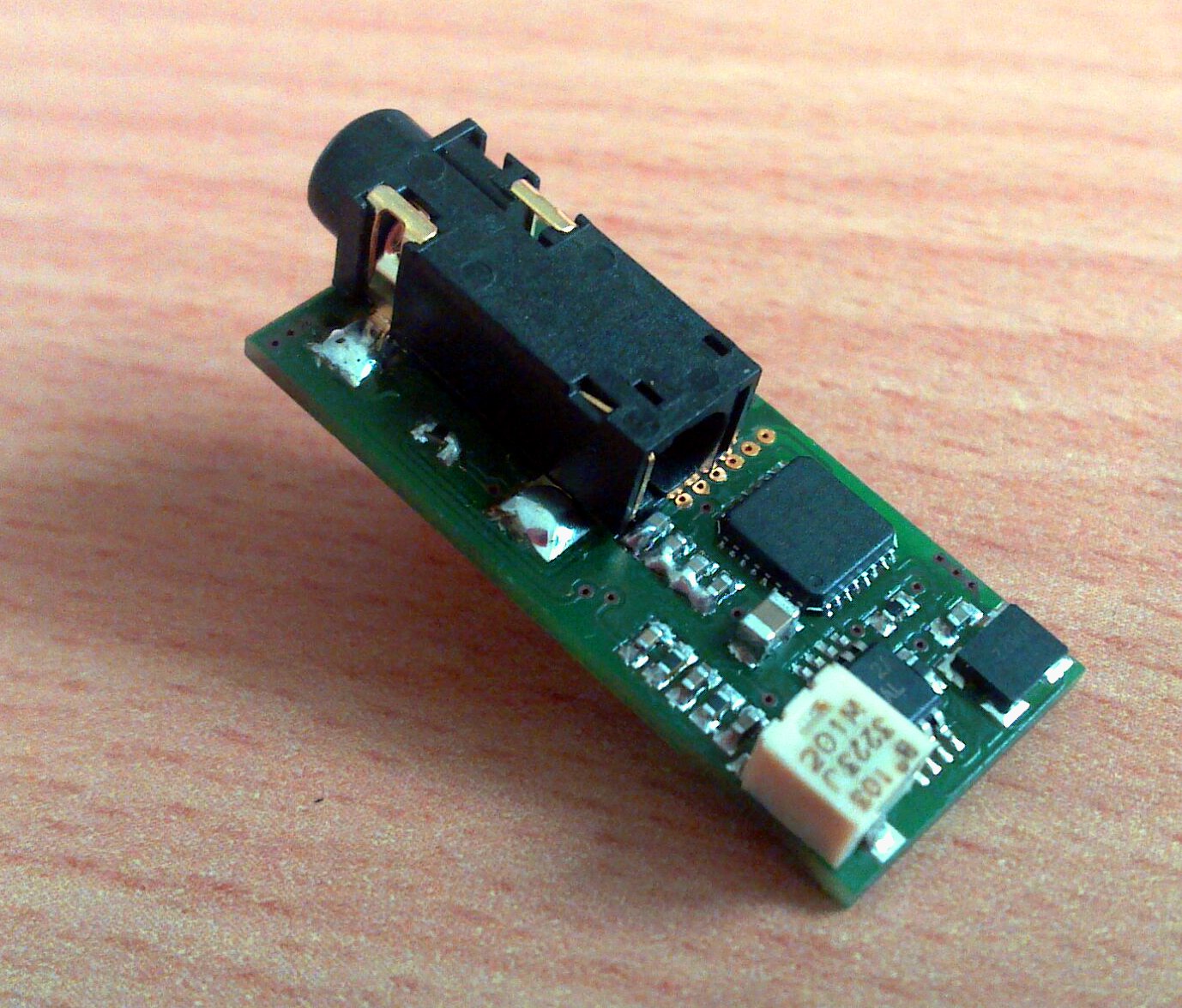
Hardware details of the AudioAmp Extension
There are a few facts that are important to know when working with the AudioAmp Extension.
- The AudioAmp board features it's own microcontroller, the Mozzi Controller. This controller is also an Arduino and you can upload your Mozzi Sketches to it. This allows you to free a lot of space on the Base Module Controller, because the sound synthesis will be done on the Mozzi Controller. The Base Module Controller could just simply send sensor values to the Mozzi controller, which then generates the sound.
- Second, the AudioAmp Extension features an amplification chip, the TPA2005D1. This allows you to connect speakers to the module instead of headphones, but is optional. The volume control potentionmeter will only affect the volume if you use the amplification chip.
- Third, the module is highly flexible and can be configured in various ways using two-way solder jumpers. This means you can apply a little blob of solder on a certain location of the circuit board in order to configure a connection between 3 wires. This means of course to rework the hardware.
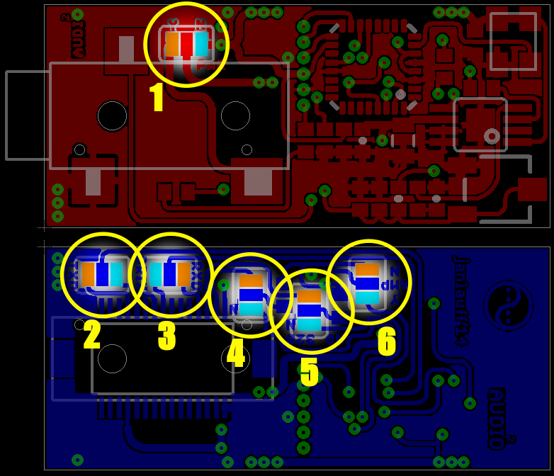
Hardware Configuration by Solder Jumpers
The two-way solder jumpers on the AudioAmp Extension consist of a center pad and two outer pads, in the image colored in orange or light blue. You can switch the state by either putting a blob of solder between the center and orange or the center and light blue. This will later be referred to as the states OR and LB. The solder jumpers themselves will be referred to by their yellow label number (1-6). In some cases, no connection is a third, valid state. In the image, the upper dark red PCB is the top side (see the audio jack) and the lower dark blue PCB is the bottom side of the AudioAmp Extension.
| Jumper | Description | OR | LB | Effect |
| 1 | Amplifier/Speaker Power Supply | X | The amplifier chip and the connected speaker are powered externally (see [External_Power]] | |
| 1 | Amplifier/Speaker Power Supply | X | The amplifier chip and the connected speaker are powered with 3.3V from the BRIX₂ Base Module. Please pay attention to the BRIX₂ Base Module Maximum Ratings | |
| 1 | Amplifier/Speaker Power Supply | The amplifier chip is not powered at all. This works only if jumper 6 is set to OR. | ||
| 2 | Serial Connection TX | X | The TX line of the AudioAmp Controller is connected to the SCK pin of the User Controller (see BRIX₂ Base Module Extension Ports), allowing a software serial connection | |
| 2 | Serial Connection TX | X | The TX line of the AudioAmp Controller is connected to the TXD pin of the User Controller (see AudioAmp Extension Communication for a fix. | |
| 2 | Serial Connection TX | Serial transmission from the AudioAmp Extension to the Base Module is deactivated | ||
| 3 | Serial Connection RX | X | The RX line of the AudioAmp Controller is connected to pin D11 of the User Controller (see BRIX₂ Base Module Extension Ports), allowing a software serial connection | |
| 3 | Serial Connection RX | X | The RX line of the AudioAmp Controller is connected to the RXD pin of the User Controller (see AudioAmp Extension Communication for a fix. | |
| 3 | Serial Connection RX | Serial transmission from the Base Module to the AudioAmp Extension is deactivated | ||
| 4 | Dual PWM Pin 1 | X | PWM1 signal (see http://sensorium.github.io/Mozzi/learn/output/) for the sound synthesis is created by the Base Module pin D9 (synthesis is done by Base Module). | |
| 4 | Dual PWM Pin 1 | X | PWM1 signal (see http://sensorium.github.io/Mozzi/learn/output/) for the sound synthesis is created by the AudioAmp Controller pin D9 (synthesis is done by AudioAmp Extension Controller). | |
| 5 | Dual PWM Pin 2 | X | PWM2 signal (see http://sensorium.github.io/Mozzi/learn/output/) for the sound synthesis is created by the Base Module pin D10 (synthesis is done by Base Module). | |
| 5 | Dual PWM Pin 2 | X | PWM2 signal (see http://sensorium.github.io/Mozzi/learn/output/) for the sound synthesis is created by the AudioAmp Controller pin D10 (synthesis is done by AudioAmp Extension Controller). | |
| 6 | Sound Output | X | No amplified output at audio jack, works great for headphones. | |
| 6 | Sound Output | X | The synthesized audio signal is amplified. Use this option if you connect speakers. Note that the amplifier chip needs to be powered properly, see jumper 1 |
No Controller, no amplification (Default Setting)
The Audio synthesis has to be done on the Base Module Controller, which is basically just connected to the left channel of the headphone jack on the AudioAmp Extension just as in this schematic: https://farm8.staticflickr.com/7458/10657009473_26c1f478de.jpg, taken from http://sensorium.github.io/Mozzi/learn/output/
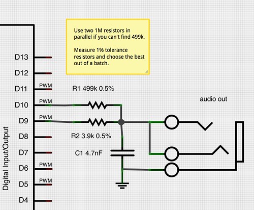
Mozzi Controller, no amplification
Amplification active
(Default settings)
The default settings of the AudioAmp Extension are: Mozzi HiFi mode on pins D9 and D10, as advised on http://sensorium.github.io/Mozzi/learn/output/ . The amplification is not active by default, the audiojack (left channel) is directly connected to the microcontroller audio output circuit.
Amplification
Communication with the AudioAmp module
The AudioAmp Extension is flexible in it's ways of communicating with the BRIX₂ Base Module. By default, it communicates using a Software Serial implementation with the Base Module pins SCK and D11 (RX/TX). There is also the option to jumper the communication to the hardware serial lines on the Base Module (RXD, TXD). This means you can communicate much faster and easier, but you would use the same communication line that the User Controller uses to communicate with the System Controller. So if you send data that way, it will also be picked up by the System Controller. That is no issue as long as System Controller AND the AudioAmp module are just listening. If one of them starts 'talking', a short-circuit is likely.
Due to an error in the design, if the communication is jumpered to hardware RX/TX, the RX/TX lines need to be swapped. This means you basically have to connect jumper 2 center to jumper 3 LB and jumper 3 center to jumper2 LB. All current modules should have that fix installed.
Uploading sketches to the AudioAmp Controller
If your AudioAmp Controller is configured to use Hardware Serial, you can just upload the >Tools>AudioAmp_Traverse sketch to your User Controller. Then select "Arduino Duemilanove w/ATmega328" as a Board and upload your Mozzi sketch to the AudioAmp Extension. Regardless if you are using a Hardware Serial or Software Serial connection to upload your sketches to the AudioAmp Extension, you need to patch your Arduino IDE (as of July 2014). > Patch beschreiben!!!! <
Patching the Arduino IDE
In order to program the BRIX2 System Controller via the Serial_Traverse sketch, you will need to patch a file (as of Arduino 1.0.4). You can follow the instructions on http://petervanhoyweghen.wordpress.com/2012/11/08/using-the-leonardo-as-usb-to-serial-converter/ or this local copy:
Locate the CDC.cpp file (arduino-1.0.n/hardware/arduino/cores/arduino) and add the lines printed in bold (a patch-file is attached to this page):
void WEAK lineCodingEvent(long baud, byte databits, byte parity, byte charFormat){}void WEAK lineStateEvent(byte linestate){}bool WEAK CDC_Setup(Setup& setup){
u8 r = setup.bRequest;u8 requestType = setup.bmRequestType;if (REQUEST_DEVICETOHOST_CLASS_INTERFACE requestType){
if (CDC_GET_LINE_CODING r){
USB_SendControl(0,(void*)&_usbLineInfo,7);return true;
}
}if (REQUEST_HOSTTODEVICE_CLASS_INTERFACE requestType){
if (CDC_SET_LINE_CODING r){
USB_RecvControl((void*)&_usbLineInfo,7);lineCodingEvent(_usbLineInfo.dwDTERate,_usbLineInfo.bDataBits,_usbLineInfo.bParityType,_usbLineInfo.bCharFormat);return true;
}if (CDC_SET_CONTROL_LINE_STATE == r){
_usbLineInfo.lineState = setup.wValueL;lineStateEvent(_usbLineInfo.lineState);// auto-reset into the bootloader is triggered when the port, already// open at 1200 bps, is closed. this is the signal to start the watchdog// with a relatively long period so it can finish housekeeping tasks// like servicing endpoints before the sketch endsif (1200 _usbLineInfo.dwDTERate) {
// We check DTR state to determine if host port is open (bit 0 of lineState).if ((_usbLineInfo.lineState & 0x01) 0) {
*(uint16_t *)0x0800 = 0x7777;wdt_enable(WDTO_120MS);
} else {
// Most OSs do some intermediate steps when configuring ports and DTR can// twiggle more than once before stabilizing.// To avoid spurious resets we set the watchdog to 250ms and eventually...
AudioAmp Extension is configured for Software Serial
In order to be able to upload sketches to the AudioAmp Extension via the software serial interface, you have to
- Patch the Arduino IDE (only once)
- Apply a special Bootloader (only once)
- Upload a special sketch to the User Controller (if it is not already present)
Patching the Arduino IDE
In order to be able to upload sketches to the AudioAmp Extension via the software serial interface, you have to modify a file in your Arduino directory. This has to be done only once, of course.
The file is /arduino-1.0.x/hardware/arduino/boards.txt and you'll have to add the following lines (somewhere):
##############################################################

audioamp.name=Audio Amp Extension

audioamp.upload.protocol=arduino
audioamp.upload.maximum_size=30720
audioamp.upload.speed=4800

audioamp.bootloader.low_fuses=0xFF
audioamp.bootloader.high_fuses=0xDA
audioamp.bootloader.extended_fuses=0x05
audioamp.bootloader.path=atmega
audioamp.bootloader.file=ATmegaBOOT_168_atmega328.hex
audioamp.bootloader.unlock_bits=0x3F
audioamp.bootloader.lock_bits=0x0F

audioamp.build.mcu=atmega328p
audioamp.build.f_cpu=16000000L
audioamp.build.core=arduino
audioamp.build.variant=standard

##############################################################
After that, restart the Arduino IDE and check the Tools>Boards menu for the new entry. You should be able to select "Audio Amp Extension" as a board.
Installing the Bootloader
Use a compatible flash adapter to install the slow serial bootloader that can be found in the Repository at /Firmware/Bootloaders/AudioAmp_4800_Bootloader.hex.
Flash the bootloader to the chip using AVRDude:
(NOTE: Avrdude may not know this device.)
avrdude -p m328p -P /dev/ttyS0 -U flash:w:AudioAmp_4800_Bootloader.hex.hex
After that, set the correct fusebits:
avrdude -p m328p -P /dev/ttyS0 -U lfuse:w:0xE0:m -U hfuse:w:0xDA:m -U efuse:w:0xFD:m
Avrdude may throw an error like:
avrdude: safemode: efuse changed! Was fd, and is now 5Would you like this fuse to be changed back? [y/n]
In that case, just press ENTER.
Try everything out:
avrdude -p m328p -P /dev/ttyS0 -nv
And you should get:
avrdude: safemode: lfuse reads as E0avrdude: safemode: hfuse reads as DAavrdude: safemode: efuse reads as 5
Uploading the sketch
On order to upload a sketch to the AudioAmp, you have to upload the "LiBRIX2>Tools>Soft_Serial_Traverse" sketch to the BRIX2 User Controller. After that, select"Audio Amp Extension" as board and then upload your sketch to the AudioAmp.
The sketch:
/*
 Soft Serial Traverse
 Sets the User Controller to a passthrough mode which routes
 the USB serial directly to the AudioAmp controller.
 This allows the user to talk to the AudioAmp controller via USB
 or to program the AudioAmp controller via USB and bootloader.
 */

#include <SoftwareSerial.h>
#include <BRIX2.h>

SoftwareSerial SoftSerialPort(SCK, 11); // RX, TX
BRIX2 myBrick;
static long baud = 4800;
static long newBaud = baud;
// Responsible for turning the LEDs off again
int ledCounter = 0;
int ledPeriod = 100;

#define LINESTATE_DTR  1
#define DTR_PIN 8

void lineCodingEvent(long baud, byte databits, byte parity, byte charFormat)
{
  newBaud = baud;
}

void lineStateEvent(unsigned char linestate)
{
  if(linestate & LINESTATE_DTR)
    digitalWrite(DTR_PIN, HIGH);
  else
    digitalWrite(DTR_PIN, LOW);
}

void setup() {
  myBrick.initialize();
  // Setup Serial ports
  Serial.begin(baud);
  SoftSerialPort.begin(baud);
  //Serial1.begin(baud);
  // Set DTR Pin
  pinMode(DTR_PIN, OUTPUT);
  digitalWrite(DTR_PIN, LOW);
}

void loop() {
  ledCounter ++;
  if (ledCounter > ledPeriod){
    ledCounter = 0;
    myBrick.setRGB(0,0,0);
  }
  // Set the new baud rate
  if(newBaud != baud) {
    baud = newBaud;
    SoftSerialPort.end();
    SoftSerialPort.begin(baud);
  }
  // Copy from virtual serial line to uart and vice versa
  if (Serial.available()) {
    // Receive LED on
    myBrick.setRGB(0,0,255);
    ledCounter = 0;
    char c = (char)Serial.read();
    SoftSerialPort.write(c);
  }
  if (SoftSerialPort.available()) {
    // Transmit LED on
    myBrick.setRGB(255,0,0);
    ledCounter = 0;
    char c = (char)SoftSerialPort.read();
    Serial.write(c);
  }
}
Developer Informations
Preparing a fresh AudioAmp Module
In order to install the bootloader, connect your ISP adapter to the 6 pads on the lower side of the board.
cd arduino-1.0.6/hardware/arduino/bootloaders/atmega
avrdude -B 2 -p m328p -P /dev/ttyS0 -U flash:w:ATmegaBOOT_168_atmega328.hex ; avrdude -p m328p -P /dev/ttyS0 -U lfuse:w:0xE0:m -U hfuse:w:0xDA:m -U efuse:w:0xFD:m ; avrdude -p m328p -P /dev/ttyS0 -nv
This should return something like
avrdude: safemode: lfuse reads as E0avrdude: safemode: hfuse reads as DAavrdude: safemode: efuse reads as 5
There's your bootloader.
*Status: First Tests
Bug Reports:
- Headphone Jack collides with C7 during population. Had to cut away the cones on the bottom side.
- Hardware RX/TX are swapped. TX on Mozzi controller connects to TXD of User Controller. Maybe the option should just be connecting RX of the Mozzi controller to TXD of the User Controller and restrict everything to a one-way communication. But then, the bootloader is an issue. Although we can address either System Controller or Mozzi Controller by different reset lines, they still are likely to interfere on the RX/TX lines. Maybe we could put the System Controller into a non-communication-mode first.